Technical Specifications
Parameter Specification / Typical Value
Manufacturer / Brand Eaton
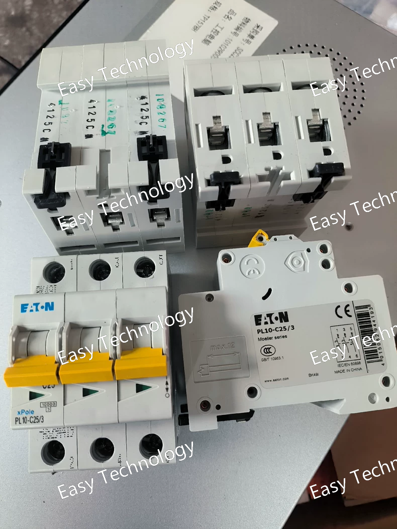
Model Number PL10-C25/3
Product Line / Series PL10
Rated Current (In) 25 A
Number of Poles 3
Tripping Characteristic C (5 - 10 x In)
Rated Operational Voltage (Ue) 400/415 V AC (3-Pole)
Rated Insulation Voltage (Ui) 500 V AC
Rated Frequency 50/60 Hz
Rated Breaking Capacity (Icn) Typically 10 kA / 15 kA @ 400V AC (Please confirm from datasheet)
Dielectric Strength 6000 V AC
Mechanical Life Typically >20,000 cycles
Electrical Life Typically >10,000 cycles
Terminal Torque As per manufacturer's manual (e.g., 2.0 - 2.5 N·m)
Mounting DIN Rail (35 mm, EN 60715)
Standards Compliance IEC/EN 60898-1, IEC/EN 60947-2, GB 10963.1
Technical Specification
Parameter Specification / Typical Value
Manufacturer / Brand Eaton
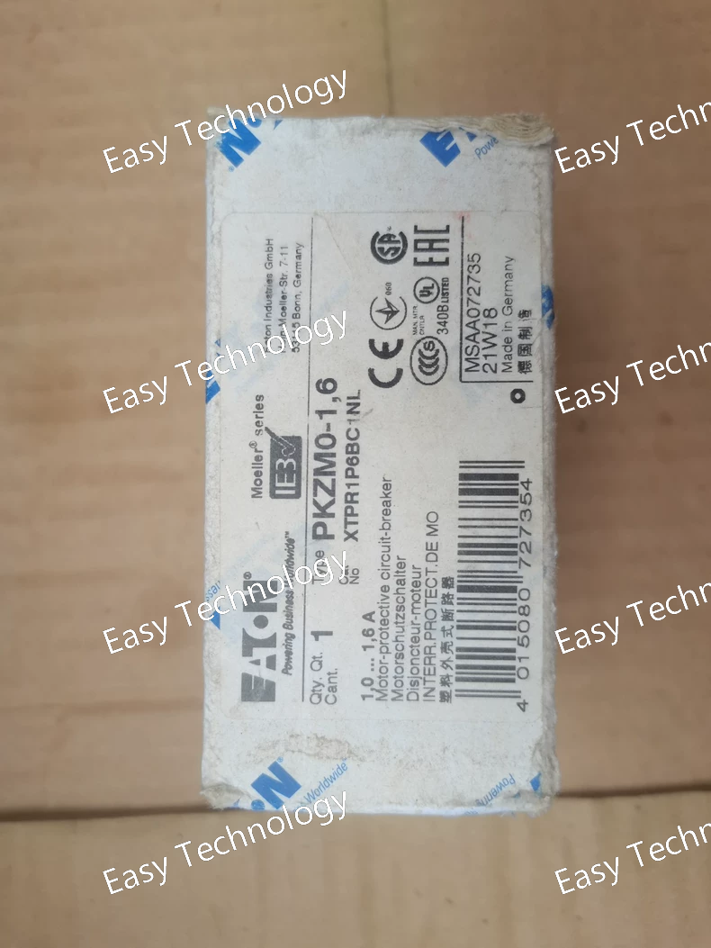
Model Number PKZMO-1.6
Product Line PKZ (Moeller Series)
Rated Operational Current for Motors (Ie) 1.6 A
Setting Range for Thermal Overload Approx. 1.0 - 1.6 A (adjustable)
Poles (Main Circuit) 3
Rated Operational Voltage (Ue) 690 V AC
Rated Insulation Voltage (Ui) 690 V / 750 V AC
Rated Ultimate Breaking Capacity (Icu/@400V) e.g., 50 kA or 100 kA (Must be verified from datasheet)
Tripping Class Class 10 (Standard for general motors, trips within 10 seconds at 7.2 x Ir)
Short-Circuit Protection Setting Fixed, based on the device design (e.g., 12 x Ie or higher)
Auxiliary Contacts Can typically be fitted with one or more auxiliary contact modules (e.g., PKZM0-1X) to signal the trip status.
Mounting DIN Rail Mount (35mm)
Standards Compliance IEC/EN 60947-2, IEC/EN 60947-4-1
Technical Specifications
Parameter Specification / Typical Value
Manufacturer / Brand Eaton
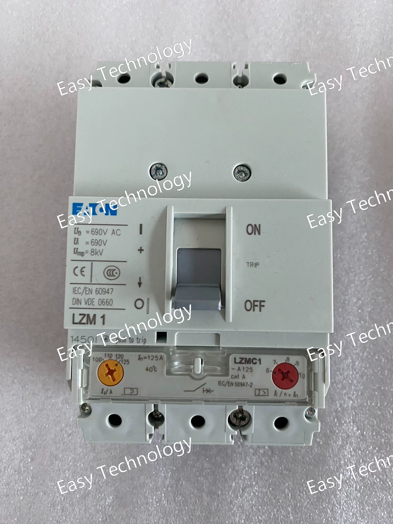
Model Number LZMC1/125A
Product Line xEffect / Standard MCCB Line
Rated Current (Iu) 125 A
Poles 3
Frame Size LZMC1
Rated Operational Voltage (Ue) 400/415 V AC (IEC) 480 V AC (UL)
Rated Insulation Voltage (Ui) 690 V / 750 V AC
Rated Frequency 50/60 Hz
Rated Ultimate Breaking Capacity (Icu) @ 400V e.g., 25 kA, 36 kA, or 50 kA (This is a CRITICAL detail that varies and must be verified from the datasheet)
Trip Unit Type Fixed Thermal-Magnetic (TMD)
Overload Protection (Ir) Fixed at 125A
Short-Circuit Protection (Im) Fixed magnetic trip setting
Installation Fixed Type
Terminal Type Stud type for cable connections
Standards Compliance IEC 60947-2, GB 14048.2, (May also have UL 489)
Torque Specification As per manufacturer's manual (e.g., ~ 30 N·m)
Technical Specifications)
Parameter Specification / Typical Value
Manufacturer / Brand Eaton
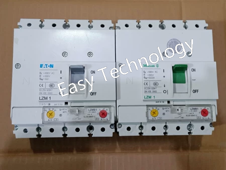
Model Number LZMB1
Product Line NZM
Device Type Electronic Trip Unit
Rated Supply Voltage Typically powered by the current transformers within the breaker (self-powered) or with an auxiliary power supply option.
Protection Functions L - Long-time Delay (Overload)
S - Short-time Delay
I - Instantaneous
G - Ground-fault
Adjustability Yes. Current settings (Ir, Isd, Ii, Ig) and time delays (tr, tsd) are fully adjustable via dials or an interface.
Display & Indication Typically an LCD or LED display for current, status, and fault information.
Communication Ready Often designed to be the base unit for adding communication modules (e.g., for Profibus, Modbus, Ethernet/IP).
Compatible Breaker Frame Sizes Designed for specific NZM frame sizes (e.g., NZM2, NZM3, NZM4). 必须与断路器本体匹配。
Standards Compliance As part of the complete breaker, it helps comply with IEC 60947-2 and other relevant standards.
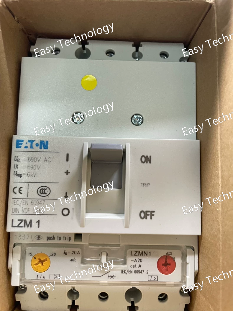
Technical Specifications
Parameter Specification / Typical Value
Manufacturer / Brand Eaton
Model Number LZMN1-A20
Product Line NZM
Rated Current (Iₙ) 20 A
Poles 3
Frame Size NZM1-A
Rated Operational Voltage (Uₑ) 400/415 V AC (IEC) / 690 V AC
Rated Insulation Voltage (Uᵢ) 690 V AC
Rated Frequency 50/60 Hz
Rated Ultimate Breaking Capacity (I꜀ᵤ) Typically 25 kA / 36 kA @ 400V (Must be verified from datasheet)
Trip Unit Type Thermal-Magnetic (Non-Adjustable)
Overload Protection (Ir) Fixed at 20A
Short-Circuit Protection (Im) Fixed magnetic trip
Installation Fixed Type
Standards Compliance IEC 60947-2
Electrical Life Several thousand cycles (e.g., 5,000)
Mechanical Life Tens of thousands of cycles (e.g., 20,000)
Terminal Torque Refer to official manual (e.g., ~ 6 N·m)
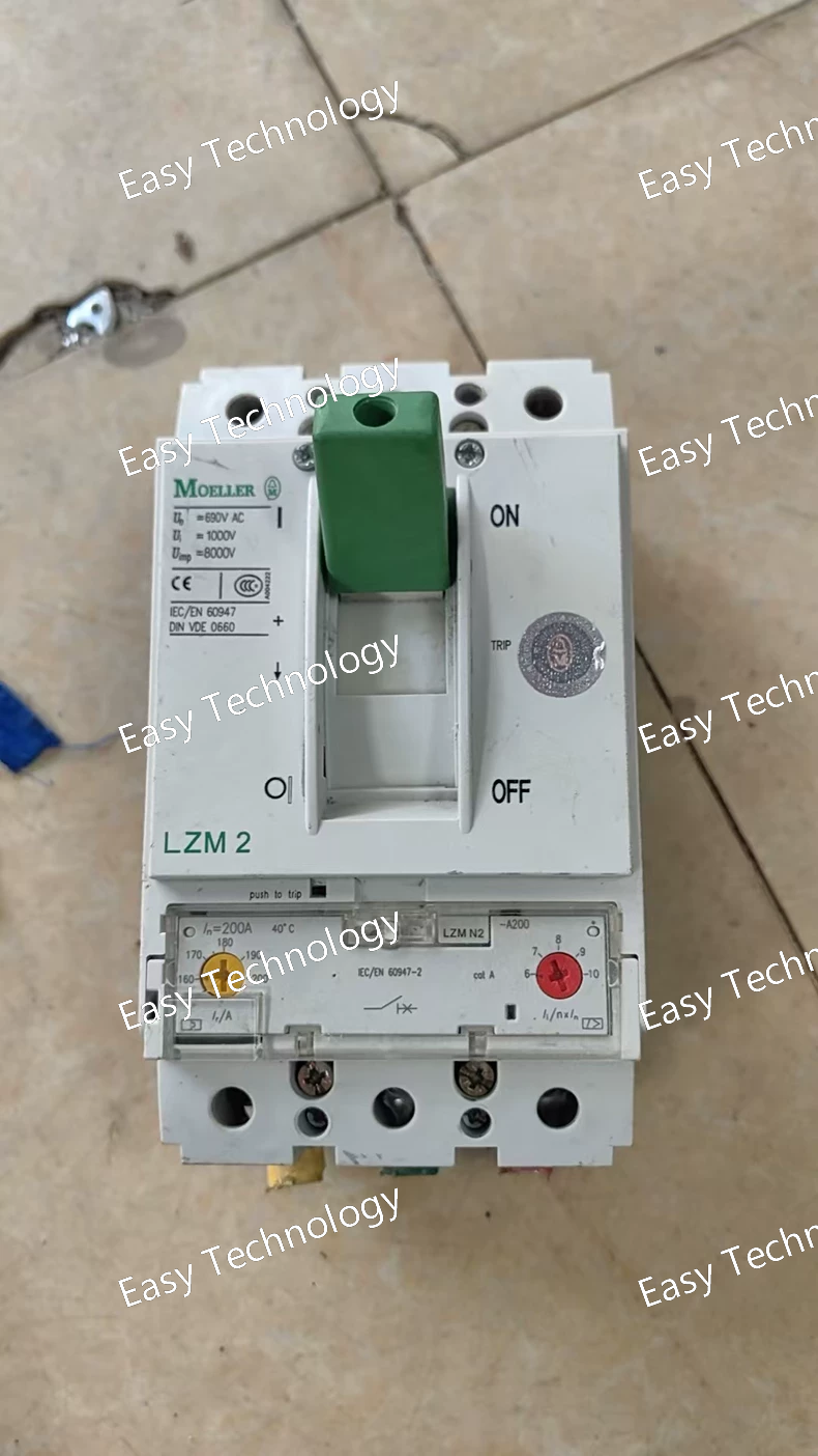
Technical Specifications
Parameter Specification / Typical Value
Manufacturer / Brand Eaton
Model Number LZMC200A
Product Line xEffect Molded Case Circuit Breaker (MCCB)
Rated Current (Iu) 200 A
Poles 3
Rated Operational Voltage (Ue) 400/415 V AC (IEC) 480 V AC (UL)
Rated Insulation Voltage (Ui) 690 V AC
Rated Frequency 50/60 Hz
Rated Ultimate Breaking Capacity (Icu) @ ...V e.g., 25 kA / 35 kA / 50 kA (This is a CRITICAL detail that varies by specific model suffix and must be verified)
Rated Service Breaking Capacity (Ics) Typically a percentage of Icu (e.g., 100% or 75%)
Trip Unit Type Thermal-Magnetic (TMD) or Electronic (MPU)
Overload Protection (Ir) Adjustable on electronic versions (e.g., 0.4 - 1 x In)
Short-Circuit Protection (Im) Adjustable on electronic versions
Installation Fixed Type (or can be mounted on a fixed base)
Terminal Type Stud type or Cable Lug (for larger conductors)
Standards Compliance IEC 60947-2, GB 14048.2, (May also have UL 489)
Torque Specification As per manufacturer's manual (e.g., 35-50 N·m for main terminals)
Technical Specifications
Parameter Specification
Model Series EZ
Valve Size 1 inch (DN25)
Pressure Class 150 LB (ANSI B16.5)
End Connections Screwed (NPT) or Flanged (configuration dependent)
Inlet Pressure Range Up to 250 psig (17.2 bar) (typical)
Outlet Pressure Range Field-adjustable (e.g., 5–60 psig or other spring-dependent range)
Flow Characteristic Self-operated (spring vs. diaphragm force balance)
Body Material Cast Iron (standard)
Trim Material Stainless Steel (standard)
Diaphragm Material Buna-N (standard)
Temperature Range -20°F to 180°F (-29°C to 82°C)
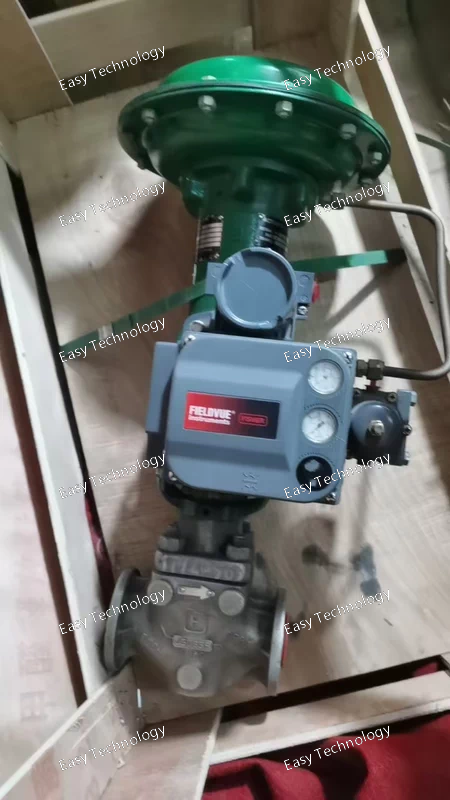
Technical Parameters
Parameter Value / Description
Manufacturer Fisher (Emerson Process Management)
Product Series DVC2000 Series Digital Valve Controller
Fisher Model 17A5515X012
Universal Model DVC2000
Action Direct Acting (Increase in input signal causes increase in output pressure).
Actuator Type Single-Acting (Non-Interspring). For spring-return or single-acting piston actuators.
Supply Pressure Typically up to 150 psig (10.3 bar).
Output Pressure Up to the supply pressure limit.
Input Signal 4-20 mA DC, with HART protocol digital superimposition.
Supply Port 1/4 in. NPT (Female)
Output Port 1/4 in. NPT (Female)
Signal Port 1/2 in. NPT (Conduit connection)
Air Consumption Low steady-state consumption (typically < 0.2 SCFM / 0.005 Nm³/min).
Air Flow Capacity High capacity for fast valve stroking.
Enclosure Rating NEMA 4X (IP66). Weatherproof, watertight, and corrosion-resistant.
Ambient Temperature Standard: -40°F to 185°F (-40°C to 85°C).
Vibration Resistance Up to 2.5 g from 10 to 150 Hz.
Mounting Direct mount on Fisher rotary and linear actuators using appropriate mounting kits.
Communication Protocol HART (Highway Addressable Remote Transducer) Protocol, Version 5, 6, or 7.
Technical Specifications
Parameter Specification
Model 12P1731X032
Type Control Valve Assembly
Valve Style Globe Valve
Valve Size Likely 1.5 inch (encoded in "1731")
Pressure Class ANSI Class 150 or 300 (encoded in model number)
Actuator Type Pneumatic Spring-Diaphragm ("X032" configuration)
Actuator Action Spring-Return (fail-safe)
Air Signal 3-15 psig (0.2-1.0 bar) standard
Flow Characteristic Equal Percentage or Linear (trim dependent)
End Connections Flanged (RF facing standard)
Body Material Carbon Steel (WCB) standard
Trim Material Stainless Steel standard
Temperature Range -20°F to 450°F (-29°C to 232°C) standard
Parameters / Specifications
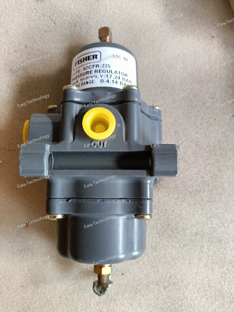
Based on the 67C Series general data and typical 67CFR variants, the likely specifications for the PF‑67CFR‑P262 are:
Model: Fisher PF‑67CFR‑P262
Series: Fisher 67C Series Instrument Supply Regulators
Construction Type: Direct‑operated regulator with filter and internal relief valve (67CFR)
Body Material: Aluminum alloy (standard for non‑stainless versions)
End Connections / Body Size: ¼‑inch NPT for inlet and outlet (standard for 67C Series)
Maximum Inlet Pressure (Body Rating): 250 psig (≈17.2 bar) for aluminum body version (all except stainless)
Maximum Emergency Outlet Pressure (Relief Margin): 50 psig (≈3.4 bar) above the set outlet pressure
Temperature Capability (depending on elastomer/filter selection):
Nitrile (NBR): approx. –40 °F to +180 °F (≈ –40 °C to +82 °C)
Fluoroelastomer (FKM): approx. 0 °F to +300 °F (≈ –18 °C to +149 °C)
Silicone (VMQ) diaphragm with low‑temperature bolting: approx. –60 °F to +180 °F (≈ –51 °C to +82 °C)
Media: Clean instrument air or compatible gases (assuming material compatibility)
Features: Filter cartridge included (part of the “F”), internal relief valve (part of the “R”), compact size, panel or inline mount capability
Approximate Weight: ~1 lb (~0.5 kg) for the ¼‑in NPT aluminum body version
Note: The exact outlet (regulated) pressure spring range for the “P262” suffix is not explicitly published in the general catalogue; typical spring ranges in the 67C Series include 0‑20 psig, 0‑35 psig, 0‑60 psig, 0‑125 psig, etc.
Additional technical data: The regulator offers excellent inlet‐sensitivity performance (e.g., less than 0.2 psig change in outlet for 25 psig change in inlet) and repeatability approx. 0.1 psig depending on elastomer.
Typical Applications: Instrumentation supply regulators for pneumatic controllers, valve positioners, air chucks, instrumentation panels.