Technical Parameters
Basic Information
Brand: ALSTOM / Converteam
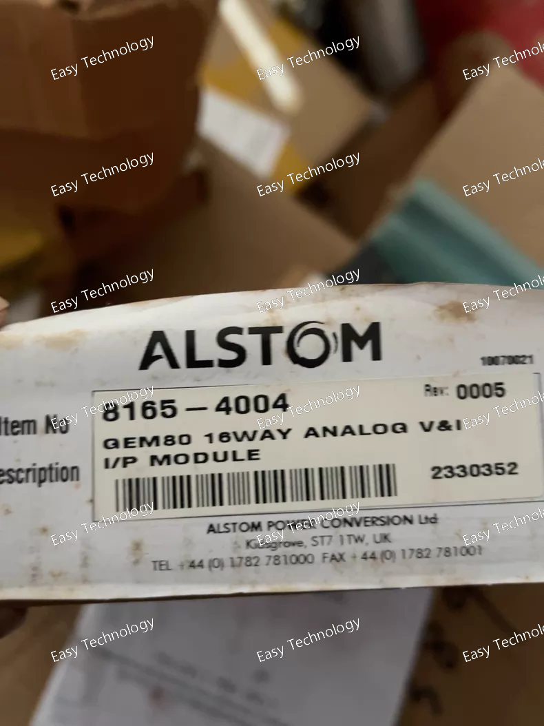
Part Number: 8165-4004
Equivalent platform model: AP5427A
Form Factor: Standard 3U slide-in rack pluggable power drive module
Matching peripheral boards: MVTU/MVTT traction master CPU, MVAJ/MVAX/MVUA high voltage auxiliary power supply, PRS12N series DC110V backup power, 8197-4002 analog sampling board, 8239-4018 digital I/O safety board, 9510-4001 TCMS communication gateway, SIR4 safety relay isolation board
Application: European urban metro & light rail traction inverter, three-phase high-power IGBT module driving, microsecond-level hardware fault protection and real-time power module thermal status feedback
Power Supply Specifications
Logic control power: DC 24V vehicle control power, operating range 18VDC ~ 30VDC
Isolated gate drive power: ±18V dedicated insulated power supplied by high voltage auxiliary power board
Total maximum power consumption: 8.4 W
Input protection: Reverse polarity blocking diode, multi-stage TVS surge absorption filter, independent input overcurrent fuse, undervoltage lockout interlock
Core Drive & Hardware Protection Functions
Multi-channel galvanically isolated IGBT gate drive outputs
Matched independent drive loops for three-phase traction power IGBTs; built-in precision matched gate resistance to balance switching speed and suppress switching loss; high peak drive current to reliably drive large-capacity traction power modules.
Microsecond-grade hardware fault detection circuit
IGBT desaturation fast shutdown (hardware response time < 2μs)
Instant primary DC-link power loop overcurrent detection and drive interlock cut-off
Real-time loss monitoring of ±18V isolated gate drive power supply
Multi-channel NTC thermistor input for real-time power module temperature monitoring
Independent hardware interlock blocking output
Once any dangerous power device fault is triggered, the board immediately locks all gate drive outputs and sends hardware-level blocking pulse to master CPU; protection action works completely independent of software algorithm to avoid permanent burnout of expensive IGBT power modules under short-circuit faults.
Fault latch & status upload mechanism
All transient and steady abnormal fault states are hardware latched; fault codes, channel enable status and temperature alarm signals are transmitted to traction master CPU through proprietary rack backplane bus for permanent fault storage and vehicle diagnostic reporting via TCMS gateway board.
Internal Rack Communication
High-speed dedicated backplane bus for bidirectional real-time data interaction with traction master CPU: receive synchronized PWM drive modulation instructions; upload drive enable status, IGBT fault flags and power module temperature alarm data.
Mechanical Specifications
Overall dimension: H130 mm × W98 mm × D220 mm
PCB protection: Full acrylic conformal coating, anti-moisture, anti-corrosion, anti-dust, anti-mold
Front panel LED indicators: Logic Power OK, Isolated Gate Power Normal, Drive Enable, IGBT Channel Fault, Power Module Overheat Alarm, Rack Bus Communication Disconnect
Fastening structure: Anti-looseness lock buckle, maintains stable electrical contact under long-term vehicle running vibration and impact
Railway Environmental & EU EN Compliance
Operating ambient temperature: -25 ℃ ~ +70 ℃
Storage & transport temperature: -40 ℃ ~ +85 ℃
Relative humidity: 5% ~ 95% non-condensing
Vibration test standard: IEC 61373 railway rolling stock
Shock resistance: 12g half-sine wave impact test
EMC standard: EN 50121-3-2 railway vehicle electromagnetic compatibility
Fire safety grade: EN 45545-2 HL2 low smoke, low toxicity flame retardant material





 home
home

 WhatsApp
