
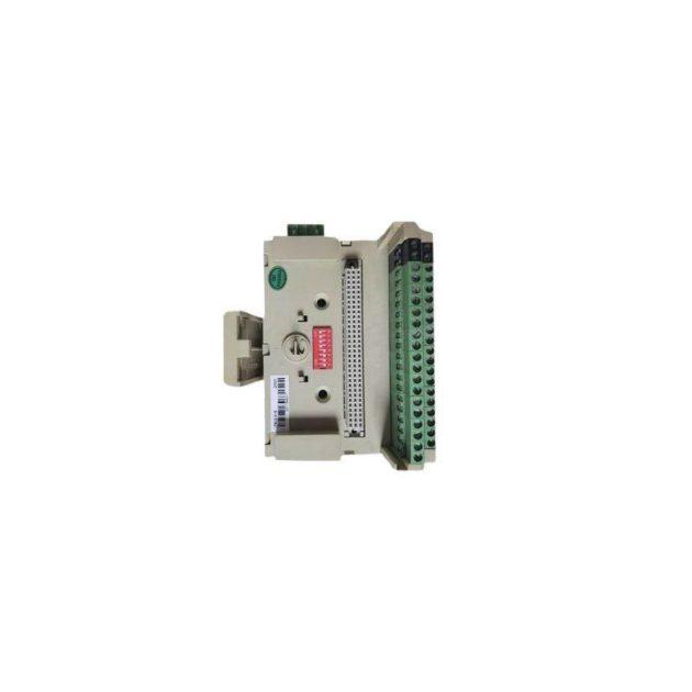
Technical Parameters
Parameter Value Notes
Maximum Operating Pressure 250 bar 3,625 psi
Rated Flow Capacity 15 L/min 4 US gpm per section
Port Size 1/2" NPTF Standard mobile connections
Spool Configuration 3-position, 4-way Spring-centered
Actuation Type Mechanical lever Manual control
Pressure Rating
- Work Ports 250 bar 3,625 psi
- Inlet Port 210 bar 3,045 psi
Leakage < 30 mL/min At rated pressure
Technical Parameters
Parameter Value / Description Notes
Thread Size / Cavity C08-2 This is the standardized cavity code per CETOP RP 121 H or ISO 7789. It defines the thread and installation dimensions.
Nominal Size 8
Maximum Operating Pressure 350 bar (5,075 psi)
Cracking Pressure (Free Flow) Typically < 0.4 bar (6 psi) Very low pressure drop in the free-flow direction.
Pilot Ratio ~ 3:1 to 4:1 (e.g., 3.5:1) A common ratio, meaning the pilot pressure required to open the valve against the load pressure is roughly Load Pressure / Pilot Ratio. This is a key specification to verify.
Maximum Flow Approx. 40 - 60 L/min (10 - 16 US gpm) Dependent on permissible pressure drop.
Seal Material Typically Nitrile (Buna-N) Standard for petroleum-based hydraulic fluids.
Technical Parameters
Parameter Value Notes
Nominal Size 8
Rated Flow 40 L/min 10.6 US gpm @ 70 bar ΔP
Maximum Operating Pressure 315 bar 4,570 psi
Supply Pressure 210 bar maximum 3,045 psi
Control Signal ±10 mA or ±10 V DC Proportional input
Hysteresis < 1.5%
Linearity < 3%
Frequency Response > 80 Hz (±45° phase lag) At 50% rated stroke
Null Leakage < 1.5 L/min At rated pressure
Technical Parameters
Parameter Value Notes
Maximum Operating Pressure 350 bar 5,075 psi
Rated Flow Capacity 19 L/min 5 US gpm
Port Size NG06 CETOP 03 standard
Spool Configuration 3-position, 4-way Critical center
Solenoid Type Wet pin DC Continuous duty
Voltage 24V DC Code 60
Power Consumption 26W At 20°C (68°F)
Protection Rating IP65 Solenoid standard
Technical Parameters
Parameter Value Notes
Nominal Size 16 Standard interface dimension
Maximum Flow Rate 40 L/min 10.6 US gpm (typical)
Minimum Controlled Flow 2 L/min 0.5 US gpm (typical)
Maximum Operating Pressure 315 bar 4,570 psi
Control Signal 0-10V DC or 4-20mA Proportional analog input
Hysteresis < 3% Typical value
Linearity < 5% Typical value
Response Time < 50 ms To 90% of commanded value
Operating Temperature -20°C to +70°C -4°F to +158°F
Technical Parameters Code Segment Description Specification
DG4V Valve Series 4-Way Directional Valve
3 Size NG03 (CETOP 3) Interface
6C Spool Type Normally Closed Configuration
M Solenoid Type Wet Pin DC Solenoid (NA Standard)
U Electrical Connection Single Metric Connector
H7 Seal Material Nitrile (Buna-N) Rubber
60 Voltage Code 24V DC
Technical Parameters
Parameter Value Condition/Note
Maximum Operating Pressure 350 bar 5,075 psi
Rated Flow Capacity 20 L/min 5.3 US gpm
Port Size NG03 CETOP 3 Standard
Voltage 24V DC Code 60
Protection Rating IP65 Solenoid Standard
Spool Configuration Normally Closed All Ports Blocked in Neutral
Return Type Spring Automatic Center Return
Fluid Compatibility Mineral-based Hydraulic Oil -
Operating Viscosity 10-100 cSt Optimal Range
Technical Parameters Parameter Value / Description Notes
Nominal Size 16 ---
Maximum Operating Pressure (P, A, B ports) 350 bar (5,075 psi) ---
Maximum Operating Pressure (T port) 210 bar (3,045 psi) ---
Maximum System Flow Up to 120 L/min (32 US gpm) per inlet section Dependent on pump and system design
Recommended Maximum Flow per Section 60 - 80 L/min (16 - 21 US gpm) For optimal performance
Control Signal Proportional, typically 24V DC PWM Requires a compatible electronic controller
Solenoid Resistance ~ 5 - 20 Ohms (varies with model and coil) Check specific datasheet
Pressure Compensation Optional (Standard or Load-Independent) A key feature for consistent speed under varying loads
Hysteresis < 3% Indicates high repeatability and control accuracy
Internal Pilot Supply Standard (from inlet module) ---
External Pilot Supply Optional For special operating conditions
Port Size Typically SAE 12 (3/4") for work ports May vary
Technical Parameters
Parameter Value Notes
Nominal Size 16 Standard interface dimension
Rated Flow 16 L/min 4.2 US gpm standard rating
Maximum Operating Pressure 350 bar 5,075 psi (P, A, B ports)
Case Drain Pressure 25 bar max 360 psi maximum
Control Voltage 24V DC Proportional PWM signal
Spool Configuration 3-position, 4-way Spring-centered to neutral
Control Type Electrical proportional Infinite spool positioning
Neutral Position Typically float or closed center Depends on A-spool configuration
Port Size SAE 12 (3/4") Standard work port connections
Functional Characteristics
Proportional Control:
Provides smooth, infinite positioning between fully closed and fully open
Flow rate proportional to input current signal
Neutral Position:
Spring-centered return to neutral
Configurations available: float, closed center, or motor spool
Pressure Compensation:
Maintains consistent flow regardless of load pressure changes
Requires pressure-compensated inlet section
Typical Applications
Mobile construction equipment
Agricultural machinery
Material handling systems
Aerial work platforms
Industrial hydraulic power units
Technical Parameters
Parameter Value Conditions / Notes
Nominal Size 16
Rated Flow 6 L/min (1.6 US gpm) Standard rated flow under normal conditions
Max Operating Pressure 350 bar (5,075 psi) At P, A, B ports
Max Case Pressure 25 bar (360 psi) Maximum allowable case drain pressure
Control Signal 24V DC PWM Proportional input signal
Spool Type B-spool Specific directional and metering function
Spool Positioning Proportional Infinite positioning between min and max
Return Type Spring-centered Automatically returns to neutral when de-energized
Electrical Connector ISO 4400 Standard industrial connector
Seal Material Nitrile (standard) Compatible with mineral-based hydraulic oils
Functional Description
Proportional Control: Allows smooth and precise adjustment of flow and direction by varying the input current to the solenoid.
Spring-Centered Neutral: Automatically returns the spool to the neutral position when the solenoid is de-energized.
Modular Design: Can be stacked with other EPV sections to create a compact multi-function valve bank.
B-Spool Function: Provides specific metering characteristics in A and B ports for controlled actuator movement.
Typical Applications
Mobile hydraulic systems (construction and agricultural machinery)
Industrial hydraulic power units
Material handling equipment
Factory automation systems
Technical Parameters
Parameter Value / Description Notes
Thread Size / Cavity C10-12 This is the standardized cavity code per CETOP RP 121 H or ISO 7789. It defines the thread and installation dimensions.
Nominal Size 12
Maximum Operating Pressure 350 bar (5,075 psi)
Cracking Pressure (Free Flow) Typically < 0.4 bar (6 psi) Very low pressure drop in the free-flow direction.
Pilot Ratio ~ 3:1 to 4:1 (e.g., 3.5:1) A common ratio, meaning the pilot pressure required to open the valve against the load pressure is roughly Load Pressure / Pilot Ratio. This is a key specification to verify.
Maximum Flow Approx. 75 - 100 L/min (20 - 26 US gpm) Dependent on permissible pressure drop.
Seal Material Typically Nitrile (Buna-N) Standard for petroleum-based hydraulic fluids.